Where did I meet you?
To be honest, I’m not really sure how I came across Ben Akrins’ awesome PlottyBot project, but I’m sure glad I did! Maybe it was the post I saw on Toms Hardware or on Reddit. Either way, it got my attention and definitely struck a chord with me for a few reasons. It took me back to a time when I was in school (maybe junior high, maybe earlier) and just learning about some of the cool things you could do with computer assisted drawing - maybe it was the Turtle language - I can’t quite remember - it’s been a while since Junior High! Anyway there was something nostalgic about it for me.
To be honest, I needed a new project like I needed a new hole in my head. I’ve got a few younger children, I’ve got a few hobbies that already take up a bunch of my nearly non-existent free time, and I don’t have tons of space to put some new doodad that will leave my wife scratching her head (I’ve already got a reputation you see).
But we’re still in Covid lockdown, I can make some cool art for the kids and maybe spark some of their creativity and interest in building, plus it would be sooooo coool!
So, why take on this project?
- Nostalgia!
- I’ve been thinking about building a new 3D printer and and wanted to see if I could print in ABS on my current Ender 5 Plus. I’ve read lots of post talking about needing a heated enclosure to be able to do it…
- I’ve been interested in learning more about motion control with stepper motors
- Who can resist a cool Raspberry Pi Zero based project that requires 3D printing?
- It’s pretty meta - Use a 3D printer, to print a plotter that prints cool computer generated art.
- I was very much inspired by the things Ben was making with it!
The thing that really gave me the confidence to attempt this build was the depth and clarity of the build documentation that Ben put into his creation. It’s really detailed with tons of photos, great descriptions, and a Build of Materials with links to purchase on Amazon that gave me a good sense as to how to get started, and how much it was going to cost (~$275).
A few finer points
This is not just physical hardware design, it includes plotting software too! Ben has written some web based python tooling that translates Gcode into Turtle code. This code is used to to ‘talk’ to the stepper motors via the RaspberryPi GPIO interfaces… All of this is super important as it is the bit that actually makes the plotter do stuff!
If all that’s not enough, he’s made some cool software that can capture your actual handwriting and make the plotter spit it out in realtime, and another cool web program called Mandalgaba that makes geometries that the PlottyBot can draw in realtime too.
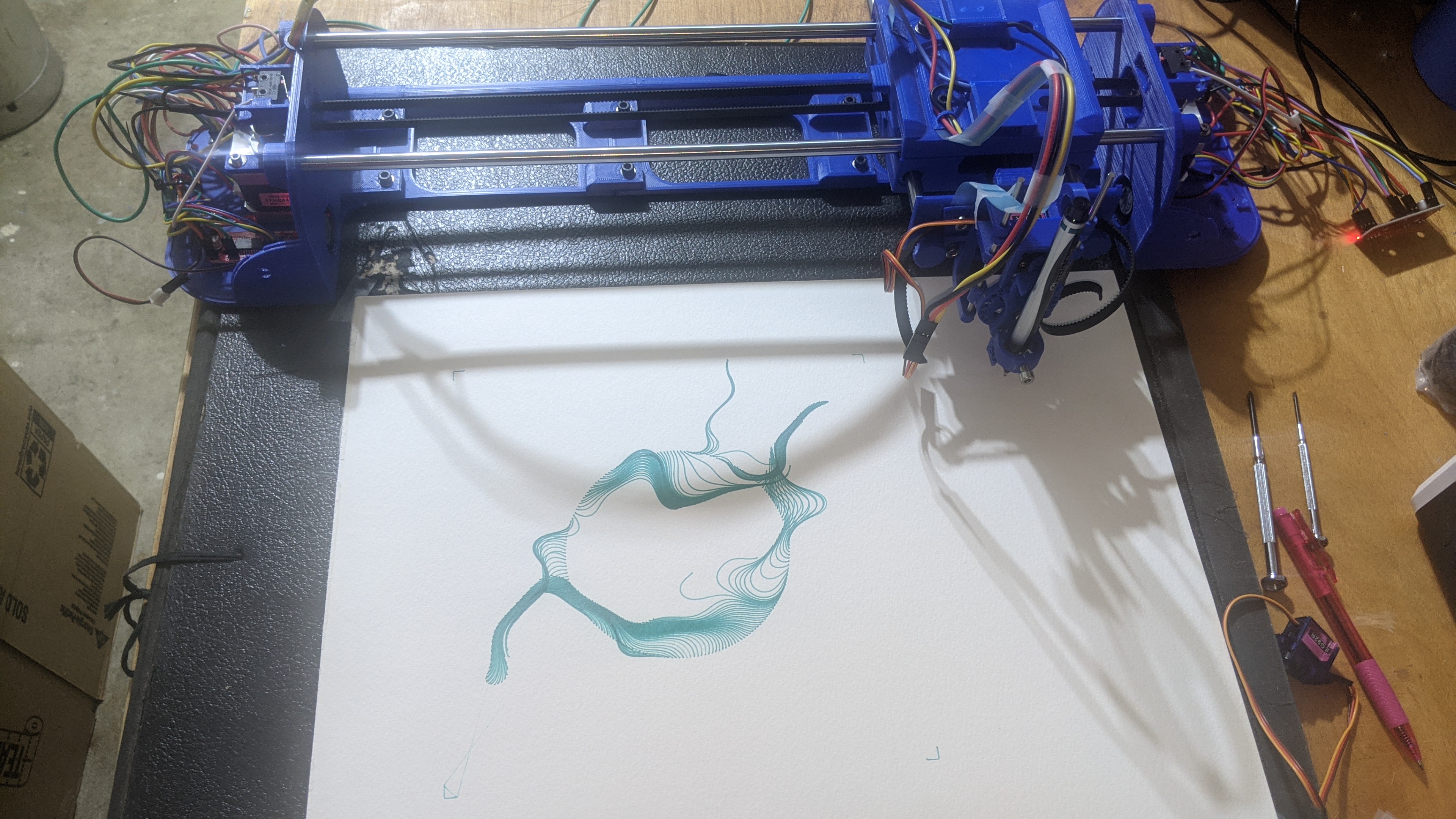
Here’s a quick video of my first plot using Mandalgaba as you draw on the web page, the plotter draws it on the paper - rad! When I let my kids go on this, they nearly lost their minds!
You can tell that this is the culmination of many many hours, months, probably years of effort from someone who is really interested in all of these things, and is also interested enough to quite generously take the time to publish his work to the internet so that maybe some other like minded, curious individuals may benefit.
Thank you Ben!
The plot thickens
(Sorry, I couldn’t help it)
Instead of putting up a bunch of pictures of my build (Ben already did an awesome job of it), I thought I’d add some of my notes / reflections on challenges I faced along the way. Hopefully anyone else considering the build (or already in the thick of things) may find some clues to help them along the way.
If there are aspects of this project that are new or challenging to you, as they were for me, know that you will get over whatever hurdle you’re currently facing and will be the better for it!
Don’t give up! Sleep on it, google it, find a way to test it, but keep pushing on, success will be your reward! =)
The Fine Print - Build Reflections
I’ll break this section down into a few areas of focus for the project including 3D Printing, Electronics, and Software.
3D printing
I greatly improved my 3D Printing knowledge/skills during this project, and I’m all the better for it. My Ender 5 Plus is better calibrated, I fixed some cooling issues with it, and dialed in my ABS printing profile. All good stuff!
All told, it took me about a week and 1Kg of filament to print out all of the parts - this includes reprinting and troubleshooting. I had many printing challenges which required tuning and testing of both the machine itself and slicer settings.
If you’re wondering about your machines print accuracy, I’d recommend starting with the ‘gondola’ parts - at least this is where I had the biggest challenges with tolerances. It’s where the 8mm linear rails and bearings come together, and it’s a really tight fit! My first prints didn’t work at all, even using a utility knife to pare back the print to accommodate the hardware. I ended up using some hammer mechanics, and split the parts along the walls. You’ll definitely need to get this component fitting together before you move on. In my opinion it’s the most challenging part with little wiggle room (Exact-o, drill, and hammer aside).
After my first failure, I didn’t want to go through another 10 hour print only for it not to work, so I decided to mock up a small box that was similar to dimensions in the gondola design where the linear bearings would go… I printed using dimensions measured in original CAD diagram, then adjusted measurements with a slight increase in tolerance until the bearing would fit snuggly, but without fear of braking the part.
Picture below shows box to the left with measurements as specified in original Sketchup design, and to the right with Horizontal Expansion set to -0.18 in Cura.
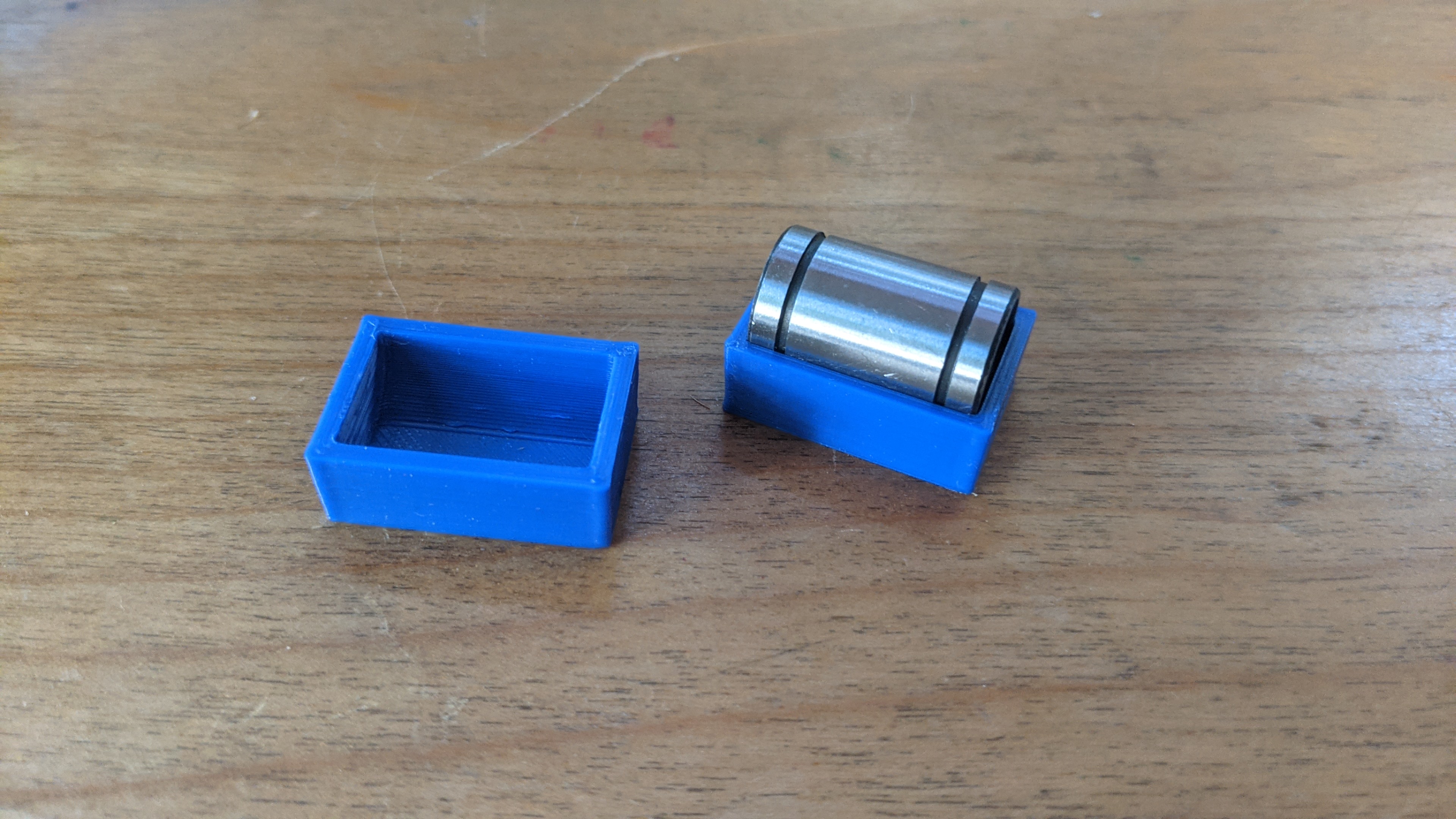
I used my final number to make slight adjustments to the ‘dimensional expansion’ settings in my slicer (Cura) to make the part just a bit bigger (.18mm), and it seems to fit the parts much better. The rail motion isn’t silky smooth, but so far isn’t causing problems. This is something I’d probably re-print to get it dialed in.
I also had similar problems with the small round ‘skateboard wheel’ style bearings. The pulley wheels they were supposed to fit in, split when using a hammer to tap them in. This one was a bit easier to simply redesign with slightly bigger tolerances for the bearing inserts (.15mm), and I was off to the races.
Misc 3D Printing notes
- I printed in ABS (Hatchbox) - It was my first time printing ABS and I wanted to see if I could do it without an enclosure as I’m considering printing parts for another 3D Printer project. They recommend printing in ABS primarily for heat tolerance and rigidity which isn’t really a requirement for this build.
- I got things pretty dialed in, but had some challenges with print tolerances, especially where the linear rail bearings fit into the gondola, and to a lesser degree for the small linear rails for the pen holder mechanism. Some parts I could clean up using an Exact-o knife, or drill.
- I had good luck with printing the larger flat pieces, but did struggle quite a bit with support removal… Maybe supports built from ABS are more difficult to remove, maybe they are just difficult =)
- I had to experiment quite a bit with part orientation in the slicer to reduce the need for support material and get good accuracy
- There was no way I could force the nuts into the holes in the parts enclosures by hand! I ended up using a smaller length bolt with washer to slowly pull the nut into place by tightening the screw - this worked well and wouldn’t stress about trying to jam the nut into it’s enclosure manually.
- If I were to print this again I’d likely use PETG. I’ve had a hard time with the strength of PLA in the past when trying to use screws/nuts, having it crack when tightening things… PETG seems to be a good compromise, a little easier to print and a little more stress tolerant. It sounds like Ben had success printing in PLA, so sounds like it’s totally doable!
- Good news is I can pretty reliably print ABS without an enclosure on my Ender 5 Pro with very minimal warpage (using fat brims) AND I identified and fixed a cooling problem that was causing major headaches in the warping department while printing ABS and PETG. The hot-end cooling fan was blowing air all over the print area - so I fixed it with this
Electronics
I learned how to make Dupont connectors - and some reasons why you may not want to use them! =) I also got somewhat better at soldering.
- I ended up accidentally getting silicon insulated wire - not a huge deal, but the wire is floppy - I primarily used 22 gauge wire which worked well, and the bundle of wires fit nicely from end to end. If you get bigger gauge wire you may have a harder time…
- I struggled a bit with getting the 4 V+ wires jammed in to the voltage regulator, probably should’ve soldered them all to a single lead and use some heat shrink tube…
- DUPONT CONNECTORS OMG! - I feel kinda silly for thinking that this would be easy, they look deceptively simple… This takes practice! Good news is I’m better at it now, but still not perfect. In the end I used a hot glue gun to keep the Dupont connectors firmly affixed to the pins on the stepper drivers / Raspberry Pi
- Wiring in general, the instructions are great, my wiring job left much to be desired… Poorly terminated Dupont connectors sometimes caused things to short circuit, or disconnect at inopportune moments. This lead to the unsavory scent of Burnt Raspberry PI and perhaps some stepper motor drivers too. See ‘Caution - Clarification’ section below…
- The choice between direct soldering and Dupont connections is legit, I do like the flexibility of being able to take things apart without having to desolder, and it was helpful to fix up my wiring mistakes… After building it once, I may opt to skip the Dupont and go straight to soldering. In the end I ended up using a hot glue gun to fix my Dupont connectors in place - still easy enough to remove, but keeps those buggers in place!
- I was a little confused as to what to expect when testing the bottom/top stepper motors. The instructions are pretty clear, they should activate 4 different times with different pitched sounds, however if you’ve got your wiring messed up, it can still appear to be working correctly but really not be correct. I believe both stepper motors should have the same behavior, activating 4 different times, each time rotating both clockwise and counter clockwise using 4 different microsteps.
A few mistakes I made and their manifestations
- Stepper motors only spinning in only one direction (clockwise or counterclockwise) ensure the DIR pin is connected to the PI correctly, switch out stepper motors or stepper motor drivers to eliminate them as source of fault (especially if you know they are working on the other side)
- One stepper motor rotating MUCH faster than the other, check the MS1/MS2 connections - they operate at TTL voltage, so if they are pinned to ground or 5v+ then they will trigger different behavior - wiring problem - can test by swapping stepper driver or stepper motor
- When testing movement, you should be able to move the gantry along the x axis while the y axis remains stationary - if not you’ve got a stepper motor problem
- Limit switches on the gondola - with the pen attachment to your right (bottom stepper motor with raspberry pi closest to you) - the limit switches on top of the gondola are in the correct orientation (left is left, right is right)
- I ended up ordering a few more stepper motor drivers, and would recommend others to do the same, Amazon offers them in pairs, or 5 packs, definitely get the 5 pack.
Caution - Clarification?
- Raspberry Pi GPIO pins are only rated for 3.3V - the stepper motor drivers by default will send 5V.
- There is a jumper on the stepper motor driver board that you can bridge with solder that will enable 3.3V instead of 5v
- Once I soldered this, I’ve yet to blow up another Raspberry Pi. I’m not sure this is the exact cause, but it certainly can’t hurt.
- The Pins from the stepper motor board to the Raspberry PI are only used for Logic Level voltage, meaning it only requires enough voltage to indicate on/off
Software
- My general lack of understanding around how stepper motor drivers worked was a limitation… I took some time to read the reference sheet for the EZ Driver, and built a little python test code to help me more safely figure things out while I was awaiting my replacement Raspberry Pi Zero (didn’t want to kill another one - even though I did!)
- Plotter software / Linux - it may be helpful for you to know where some of the code is and how it gets started - looks like there’s an /etc/rc.local script that starts up the PlottyBot web server and back end code.
- As root you can attach to the screen session to see what the software controlling the plotter is doing (screen -ls; screen -x)
- It seems that if you get into a weird state you can restart things by killing the screen session and the gpiogd process and restarting the /etc/rc.local script
- there’s the plottybot.py file in /usr/local/ if you want to see how it works.
Plotting ahead
Hopefully none of the above scare you away from pursuing this project… If you’re new to any of the above, it’s a great learning experience, and once you make it through, very rewarding.
Once you get a machine that can print Gcode - you’ll need ways to generate it. This is another art unto itself and depends largely on what you want to accomplish. I’ll share some of my generic workflows with you in another post.
For now know that I’ve been trying to do vector art in Inkscape or Adobe Illustrator - then translating that to GCode using a few different tools, parsing it so that PlottyBot knows how to translate it to Plotter Code, and have some fun!
Stay tuned - and good luck!! =)